The next project has turned out to also be a success. I had built a MOPA or two (Master Oscillator Power Amp) some years ago (more than 20 years ago) so I didn’t figure building one now to be much of a task. It turned out pretty well like I planned with only a minor hiccup or two in the process.
I had three main goals in mind before I started:
- make it simple
- make it using all tubes (even the power supply)
- make it unique (as much as possible)
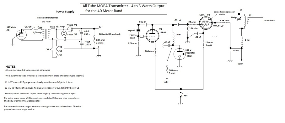
My design ended up thusly:
No power transformer for the filaments of the tubes or the main B+ supply, vacuum tube rectifiers wired as a voltage doubler, I used tubes that I had on hand in the junk box, and voltage regulation was done via a tube as well.
Here is the tube complement that I used:
2 each, 35W4 tubes (normally used as half wave rectifiers but I wired them up as a full wave voltage doubler)
1 each, 12BA6 oscillator tube (I wired it as a triode by tying together the the plate and the screen grid)
1 each, OB2 voltage regulator tube – 108 volts (for good voltage regulation on the oscillator and the screen grid of the power amplifier)
1 each, 35C5 beam power tube (the power amplifier tube in the MOPA) Note: this tube is designed as an audio output tube with a power output normally of about 1.5 watts.
The 35W4 (x 2), 12BA6, and the 35C5 tubes’ filaments wired in series came to a total of 117 volts. All of the tubes in that series are 150 ma filament draw tubes so they worked nicely powered by the normal line voltage.
With the two 35W4s doing the work of rectifying in the doubler, I was able to obtain 265 volts (under load) in the power supply. I powered the doubler with 120 volts AC.
The rig is crystal controlled, using the 40 and 30 meter band crystals I have in the junk box. The oscillator is a Pierce type (capacitively coupled from the plate to the crystal via a 500 pf capacitor)
Result: I can use the rig on 30, 40 and 60 meters as wired. Output power: two possibilities – 2 watts and 5 watts (2 watts if I use the voltage regulator in the circuit to regulate the oscillator voltage and the power output’s screen voltage, or 5 watts if I run the screen grid of the power amplifier at 140 volts instead of 108 volts , by removing the voltage regulator circuit)
The tank circuit is the simplest (and cheapest) method I could come up with: a tank circuit tuned with a variable capacitor. The inductor is wound on an old baby aspirin bottle. The antenna is link coupled via a 3 turn winding located a little below the tank coil on the form – the baby aspirin bottle)
I run the output of the MOPA through an old antenna tuner which reduces out of band harmonics to a respectable level.
At present count I have worked more than 60 stations with the MOPA transmitter on 40 and 30 meters so far. The signal tone is better than with the last Jones style rig because the crystals that I have are better suited to the very low crystal current levels in the MOPA design in comparison to the higher crystal current in the twin triode Jones style rig.
A schematic of the transmitter is shown below: